A full group of 15 gathered by the pillar box in Woking York Road (an unusual meeting place for a non-philatelic visit!) at 10.50, for the nearby visit at 11.00. The visit was also open to Railway Correspondence & Travel Society, Southern Electric Group and Signalling Record Society members. The Grade II listed 'preserved' Woking ECR is no longer operational. The building and site are retained by NR and are occasionally open for visits, including an Open House day event years ago, when I visited. Access is otherwise restricted.
https://tinyurl.com/3zwvxftd has another report and great photos which bring it all to life.
https://tinyurl.com/3bv9nh7j is an alternative report including some different images.
Woking ECR, designed by Southern Railway architect James Robb Scott, was built in 1936 for the Railway by Swedish firm ASEA (Allmänna Svenska Elektriska Aktiebolaget = General Swedish Electrical Limited Company). It was used as a control centre (along with Havant and Raynes Park on the South Western Division and later with Eastleigh ECR) after the electrification of the lines in the area but was taken out of use in 1997, although parts remain occupied. The building has a concrete frame with brick walls and metal-framed casement windows, in an International Modern style. The walls are rendered brick.
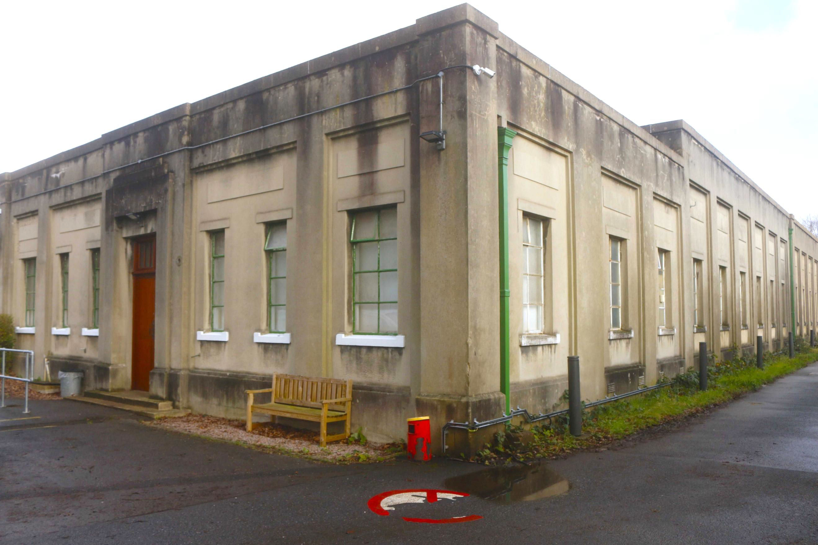
Woking Electrical Control Room.
[© Stuart Hicks 2026]The roof is a concrete slab supported by concrete beams. It comprises an entrance block of 4 x 2 bays of one storey, with a central entrance, architrave and rectangular fanlight. There is a taller one storey control room behind this. Full-height pilasters and cornice articulate the bays. There are various offices in the entrance block but the Control Room is oval with a domed ceiling. It has three ornate 1930's lamps on cast-iron columnar bases, with copper dishes which illuminate the dome as uplighters. The control room was constructed in two halves (the join in the roof can just be seen) and contains many striking Art Deco features, including copper and iron uplighters, electric supply diagrams with working lights, switches (circuit breakers) and the original control desks. It is very much stepping into another world.
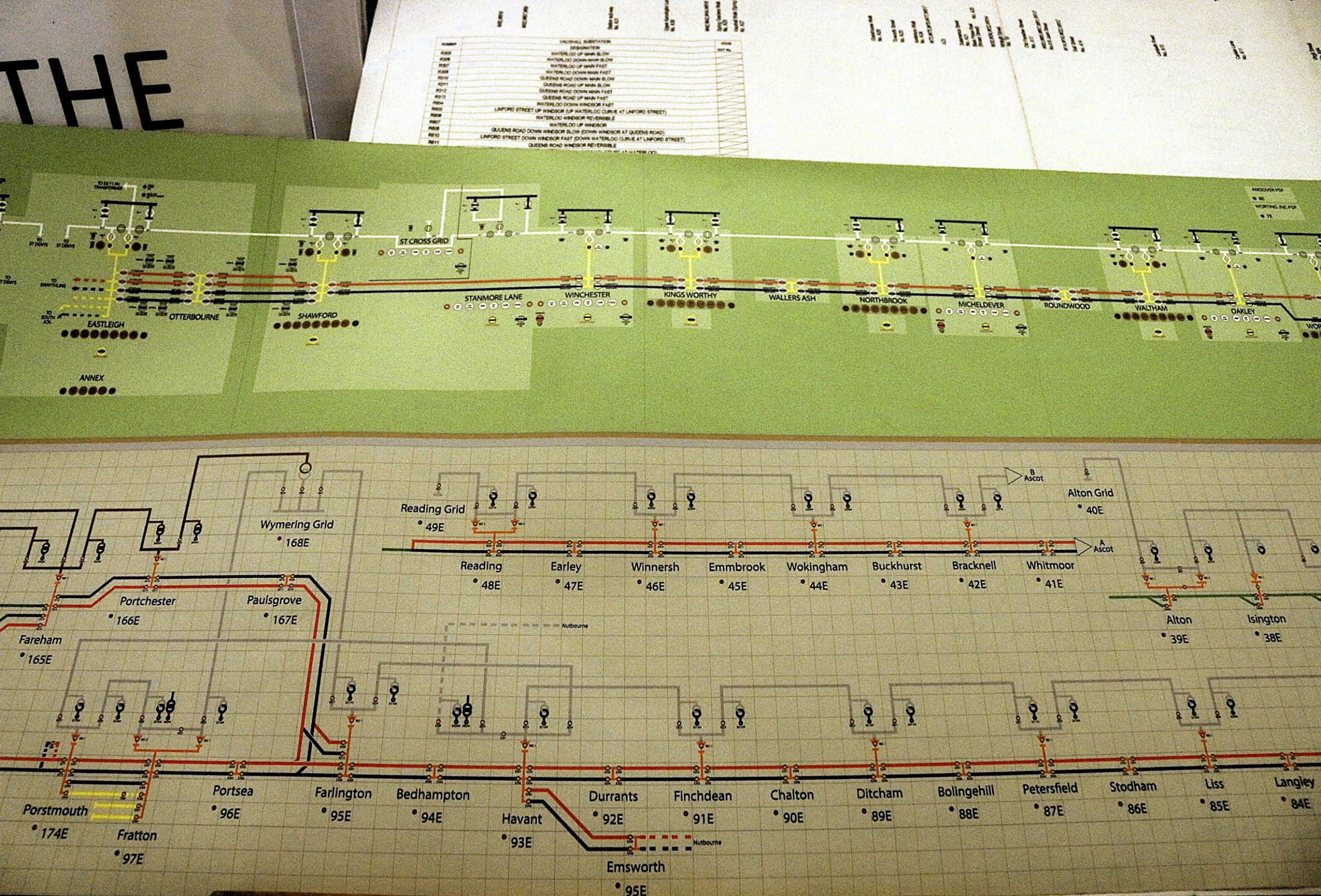
Schematic diagram of part of the electrical power distribution system showing grid connections.
[© Stuart Hicks 2026]Around the outside of the room are the track diagrams arranged in a striking design of silver against a black background with coloured lights to indicate the position of the switches (circuit breakers). Outside the room is all the original electro-mechanical switch gear. This was one of five original control rooms built for Southern Railway of which only three survive - Woking was the last one to remain operational.
Our group was met by Adam Turner who ticked us off (his list of names that is!). We were escorted into the site and met by Mark who introduced us to another two volunteer hosts. After we had signed in, we split into two groups. One (including me) with Keith, who was retired and had worked here as well as at Lewisham, Raynes Park and Eastleigh ECRs; the rest with Nigel, who still works for NR and had some responsibility for Woking in the past.
The acoustics were designed to allow the two staff normally on each eight hour shift to be able to talk to each other when standing at opposite ends of the room dealing with incidents or planned engineering work possession isolations. Not so good with two groups talking!
Most of the oval wall had electrical arrangements for the area. The eastern end is blank, and we were told that it was apparently left like this for electrification from Wokingham to Aldershot North Jn, also Shalford Jn to Reigate, which would have fringed somewhere, probably west of Dorking, with the central section control room at Three Bridges. Also, possibly, the Shalford to Horsham line. Of course, the latter is now shut and the former still not electrified, although this had been expected 'soon' in 1936!
The outside rooms had transmitting and receiving equipment, once live (not at track voltage!).
The electrical arrangements, their indications and controlling switches extend most of the way round the walls (with two small gaps for access). The routes controlled were Staines (excl) to Reading, Virigina Water to Weybridge / West Byfleet, Ascot to Aldershot / Sturt Lane Jn, Walton (-on-Thames) to Sturt Lane, Alton and Stodham (beyond Liss). At the top of the black panels is the representation of the 33kv high voltage network, with its grid feeder stations, such as Reading. At each substation, connections are provided through transformers and rectifiers into the line voltage, fed to each of the tracks concerned.
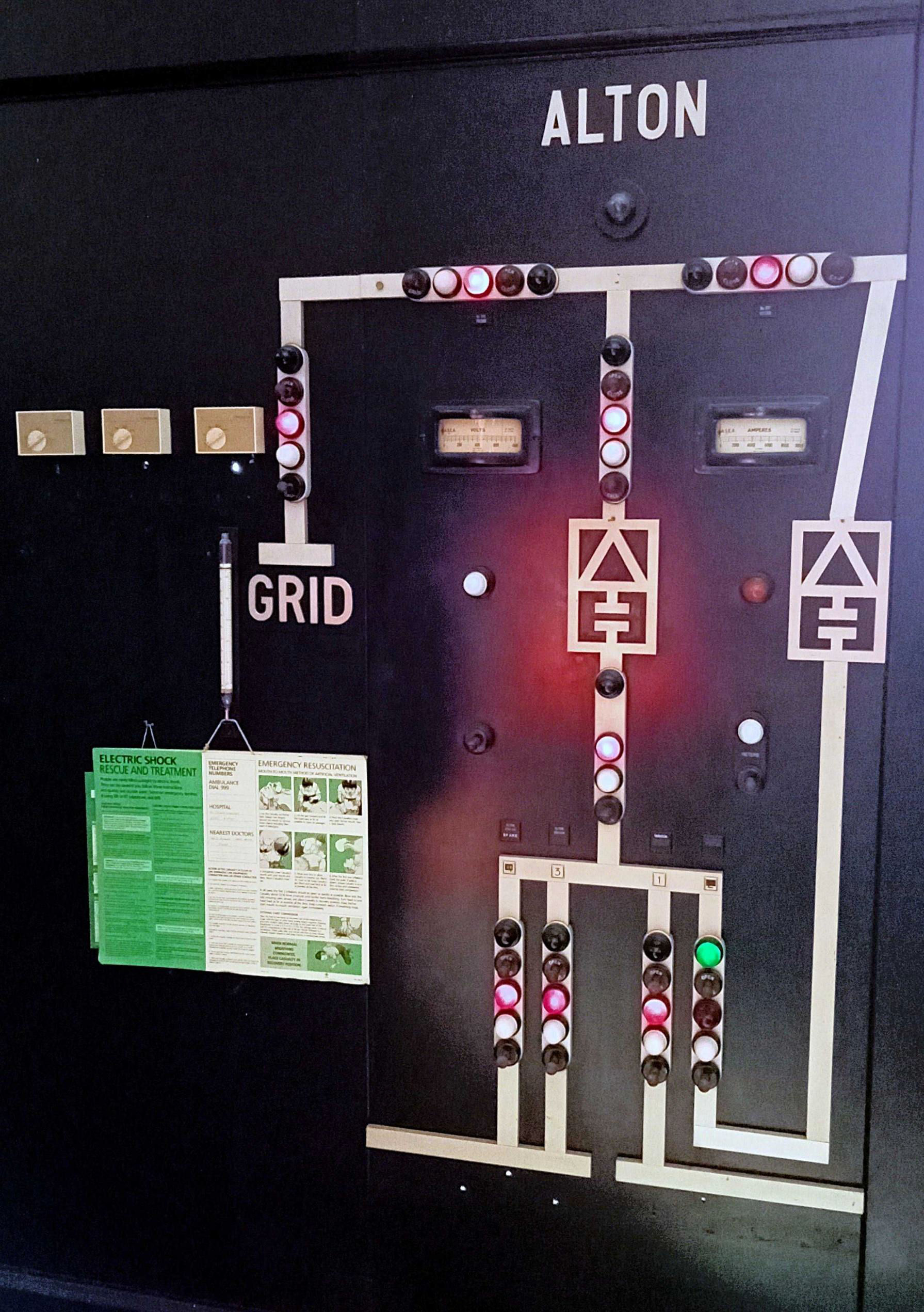
Alton electric supply diagram with coloured lights to indicate the position of the switches (circuit breakers).
[© Stuart Hicks 2026]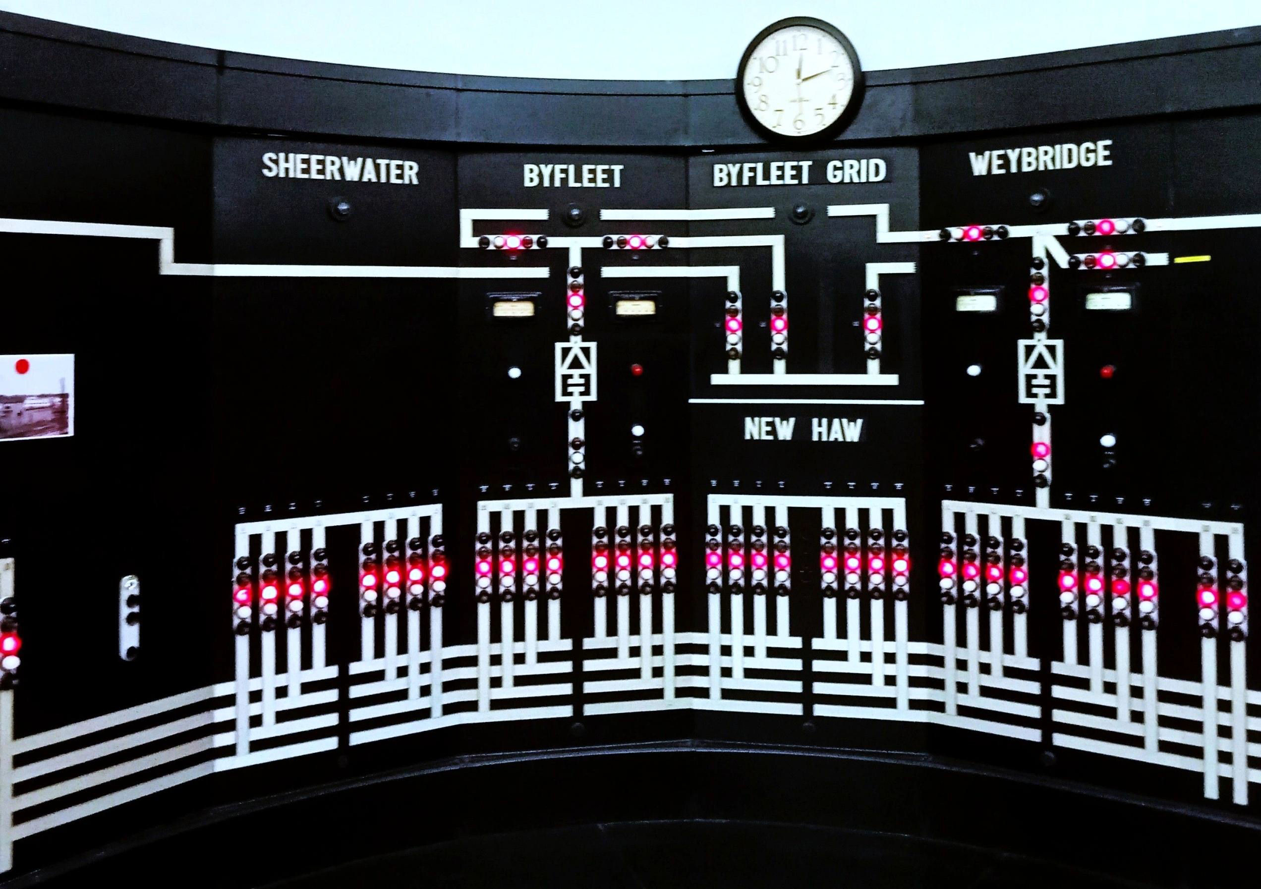
The electric supply diagrams for Sheerwater, Byfleet, Byfleet Grid, New Haw and Weybridge.
[© Stuart Hicks 2026]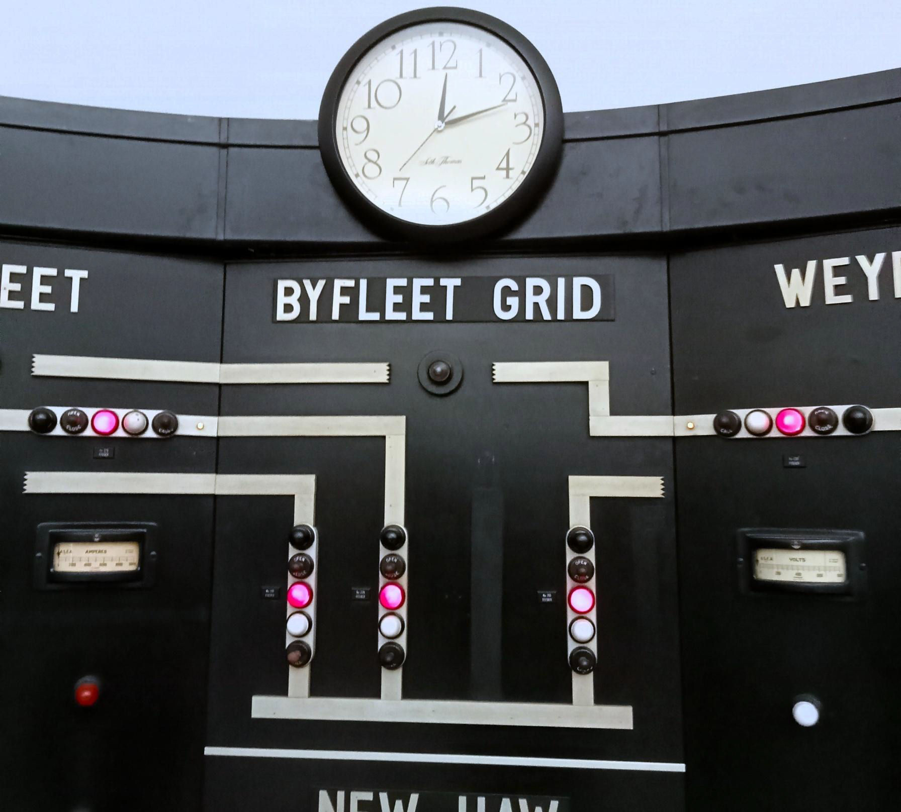
A close up of the electric supply diagram for Byfleet Grid.
[© Stuart Hicks 2026]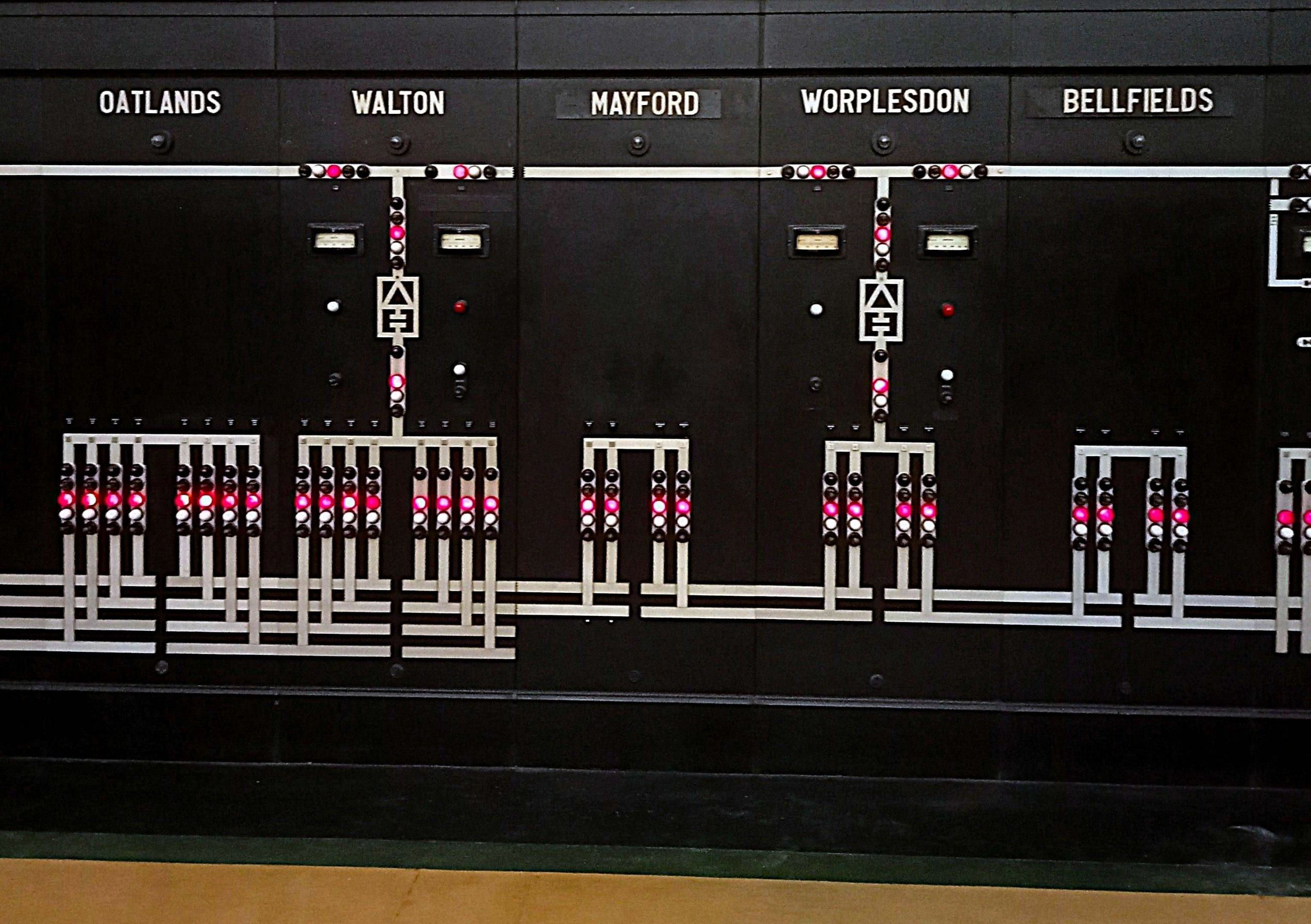
The electric supply diagrams for Oatlands. Walton. Mayford, Worplesdon and Bellfields.
[© Stuart Hicks 2026]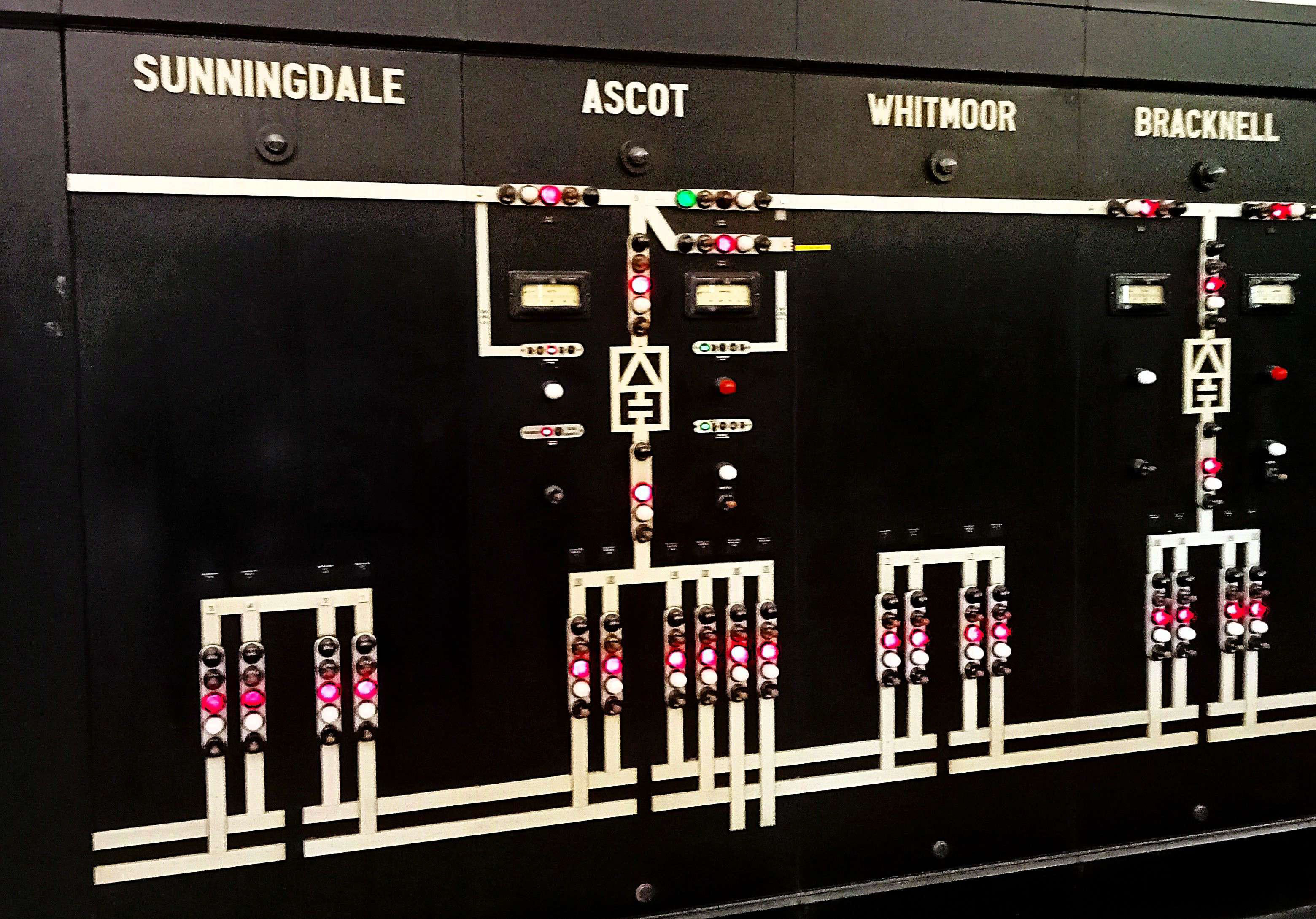
The electric supply diagrams for Sunningdale, Ascot, Whitmoor and Bracknell,
[© Stuart Hicks 2026]For example, at Reading, red lights indicate that connections are closed (live). At the bottom on the wall are connections to the conductor rails by the two (Up and Down) tracks, which are usually fed in parallel (and connected at the other end). Reading is the end of the Southern DC electrified line, of course.
Further up the line, past substations and track paralleling huts, is Ascot. This is slightly more complicated, partly due to the Bagshot branch, A green line on the grid supply shows that the switch is open to avoid the two grid connections being connected to each other. Lines towards Sunningdale and beyond are normally fed from another grid supply (Byfleet), although the break can be changed if necessary.
The Portsmouth direct line between Haslemere and Liss has alternating substations and track paralleling huts. With the power supply upgrade, many track paralleling huts (TPHs) were converted to substations.
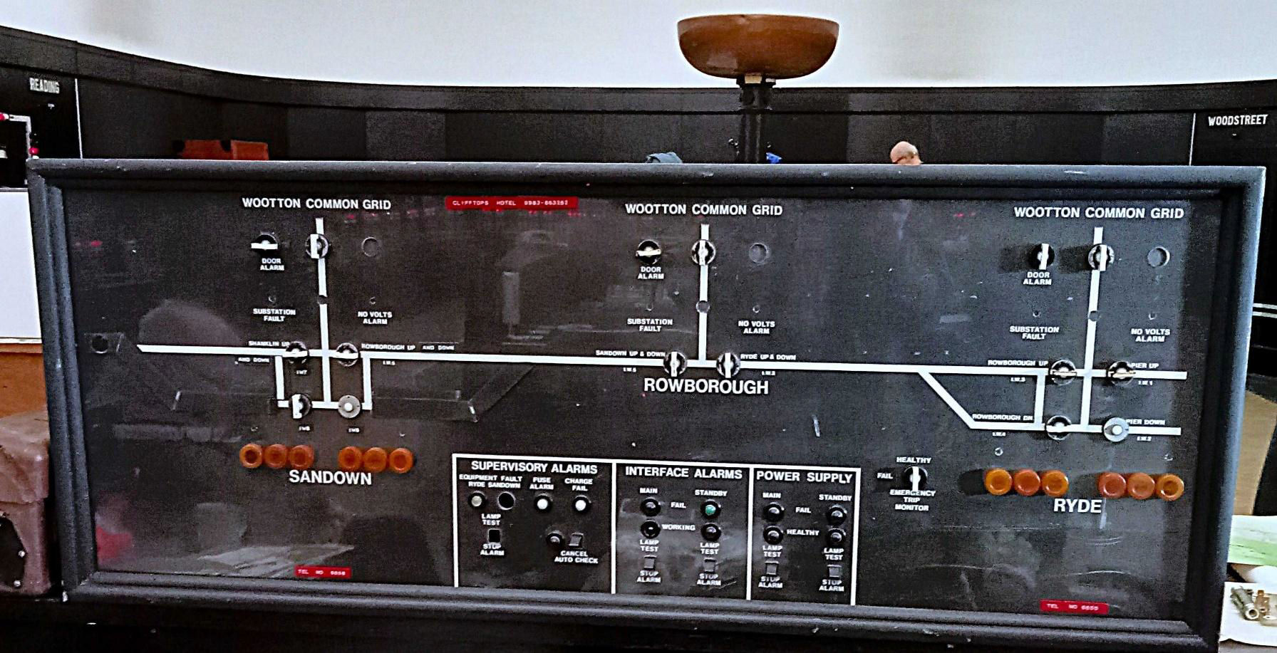
Electric supply diagram for the Isle of Wight with one of the ornate 1930's lamps in the background.
[© Stuart Hicks 2026]------------------------------------------------------------------------------------------------------------------------------------------------------------------------------------------------
Some basics: Third rail trains pick up electrical energy using metal blocks ('shoegear'), which contact and slide along the top of the conductor rail (made of special steel which conducts electricity). The conductor rail is adjacent to the running rails, raised slightly on insulators to support and keep it in position. Ramps at the start and finish of each length of conductor rail raise and lower the shoegear. There are gaps between adjacent lengths of conductor rail, or where conductor rail cannot be installed such as at level crossings. The conductor rail is supplied with 750V direct current (DC) from lineside substations between one and six miles apart. This depends on the intensity of the train service. The substations are supplied from NR's own high voltage alternating current (AC) supply system (normally 33kV) which distributes the power from the National Grid or electricity company supply points to substations for conversion to 750V DC. The system is managed to provide a resilient supply and can normally be switched to resupply substations in the event of a fault or loss of a supply point.
The conductor rail is divided into electrical sections with circuit breakers at each end. This allows remote operation, switch off or switch on of each electrical section. An electrical section is normally supplied with power at both ends of the section. This improves the efficiency and reliability of the supply to the trains. The distance between substations can be increased by installing a Track Paralleling Hut between substations. These do not input power to the conductor rail but improve the electrical efficiency of the supply by connecting parallel tracks together, balancing voltage and reducing power loss. TPHs also provide remotely operated circuit breakers to switch the power on and off. Modern third rail trains regenerate power back into the conductor rail when they brake, provided another train is taking load in a reasonable distance from the braking train (most likely nearer London). This increases efficiency.
------------------------------------------------------------------------------------------------------------------------------------------------------------------------------------------------
Our group also looked at the equipment outside of the main hall, backing onto the main room as well as transmitters and receivers that sent instructions to the outlying equipment and received confirmation that they had opened or closed the switches as instructed. For each, there were two sets of equipment which should work in synchronisation with each other; firstly, to select the outlying station to which to send instructions and then to actually send them (thus instructions could only be sent to one at a time).
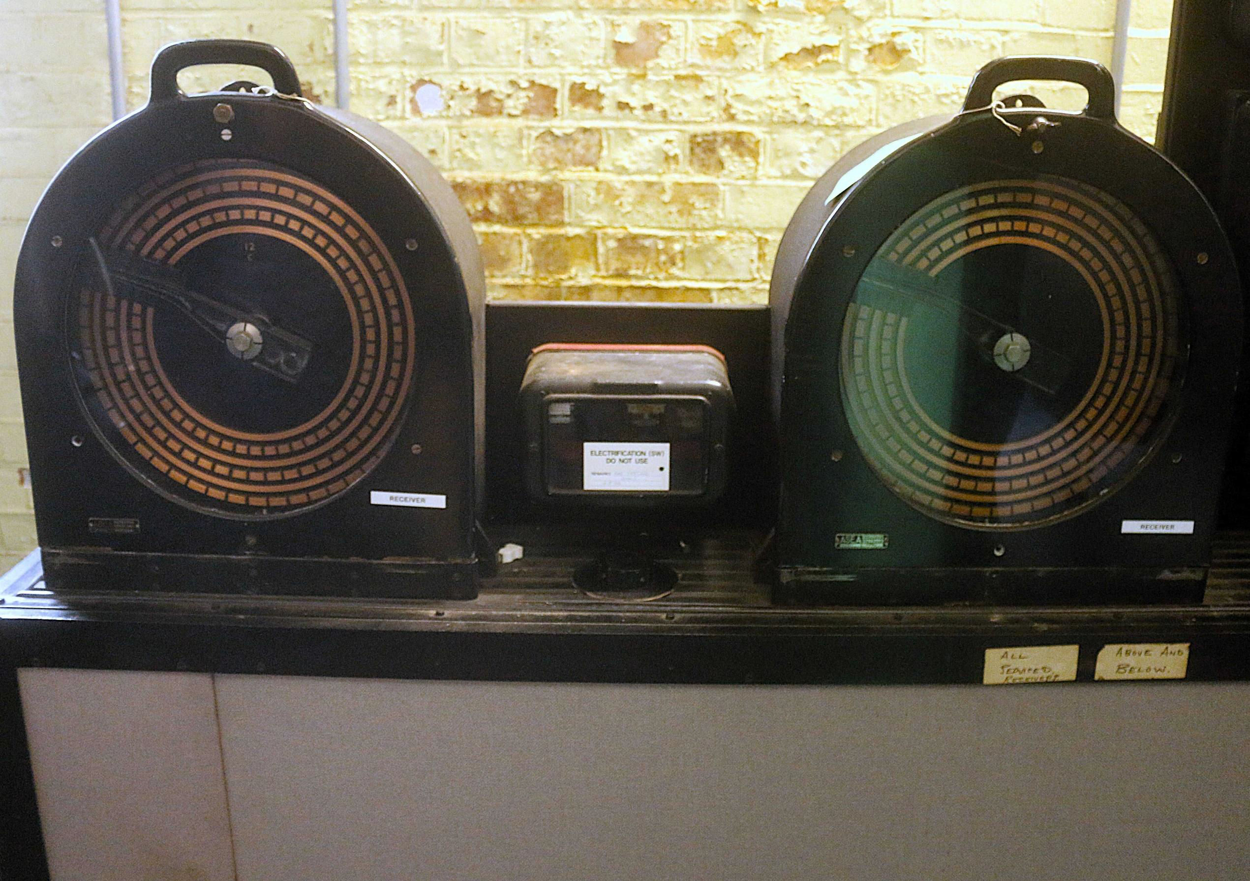
A set of two receivers situated outside the control room.
[© Stuart Hicks 2026]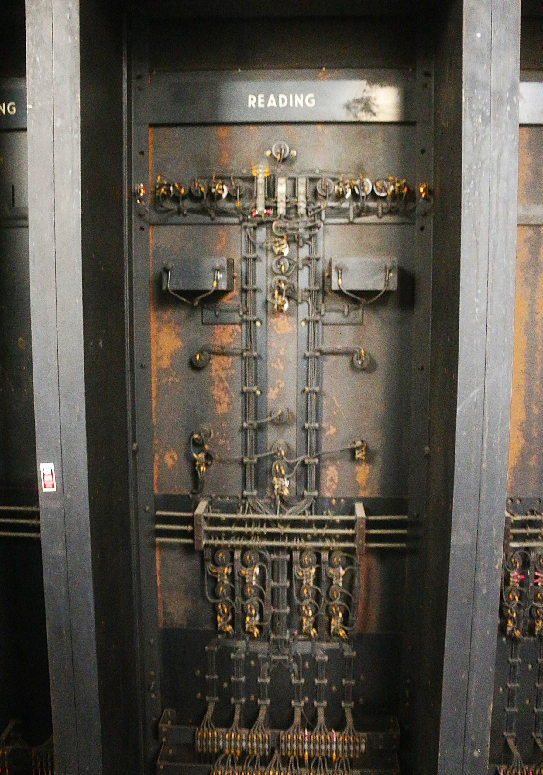
The rear of the electric supply diagram for Reading.
[© Stuart Hicks 2026]Also in the museum at the eastern end are various pieces of equipment rescued for posterity from other ECRs. Some are more recent but similar GEC (General Electric Company) selectors (from Raynes Park), which have been replaced there by electronic equipment. Some are relics from Eastleigh ECR, which is more modern (1960s Bournemouth electrification time) but since extended its control area, both 1960s original and the 1980 Searum system. There was also an extensive plan of the current Eastleigh control area, following the Weymouth and South Hampshire electrification. A lovely mercury-arc bulb was also carefully unwrapped to show our group. This was a most interesting visit; thanks to Adam Turner and our hosts, it resulted in donations of £175 to Woking Homes and £175 to Moorfields Eye Charity.